Aaron Eastman
Senior Project

Analysis
Requirements
The following requirements were set to drive the design parameters:
Confirmed Through Testing:
-
The new crusher must delaminate the carbon fiber trimmings to 100%
-
The housing of the wheel will not be displaced more than .125 inches when crushing the material
-
The feed rate of the delaminating process should be at least 1 foot per minute
Confirmed Through Analyses
-
The crushing shaft will not deflect more than .05 inches.
-
The minimum key length for the key that will transmit the torque from the sprocket and spur gear must be less than 8 inches.
-
The minimum key length for the key that will transmit the torque into the crushing wheel will be less than the hub length of 3 inches.
-
The Bearing at point C on the shaft must be able to withstand a dynamic load of 12,000 pounds.
-
The Bearing at point E on the shaft must be able to withstand a dynamic load of 5,000 lbs.
-
Each vertical frame support must have a critical failure load of over 3000 pounds.
-
The bolts attaching the bearings to the frame must not have a stress of more than 15 ksi.
-
The shaft should be precise within at least 0.05 inches and have a loose running fit.
Confirmed Through Solidworks Design and Assembly
-
Crushing wheels will have gap of 0.40 inches to start the crushing process
-
The wheels are no larger then 8 inches in diameter to keep the size of the delamination system down
-
The new crushing wheels will be aligned with the existing system with a tolerance of 0.5 inch
-
The shaft should be precise within at least 0.05 inches and have a loose running fit. (Confirmed in Manufacturing as well)
Table 1. - Summary of Analyses
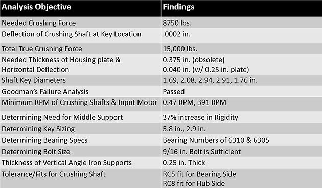
Figure 13.1
Determining Tolerances for Shaft

Completed Analyses
Analysis 1 was completed to find the amount of applied load that the crushing system has to apply to get the carbon fiber to fail in "shear". This was done by using a max shear stress equation, the max shear stress was found in order to solve for the needed applied load. The needed forced to shear the layers of carbon fiber came out to 8750 lbs.
(Figure 1)
Analysis 2 was completed to find the deflection of the shaft when the needed crushing force is applied. This was done using the beam deflection formulas because the crushing force was assumed to be a point load. The deflection was found to be .0002 in which was less than the requirement of .05 inches. This was able to confirm a shaft diameter of 2 inches is suitable for the crushing shaft.
(Figure 2)
Analysis 3 was completed to identify the amount of applied load due to the new torque of 2500 ft-lbs. This was needed to see if the carbon fiber will reach 100% delamination. This was done by finding the radial force a gear transmits due to the input torque. Calculations confirmed a diameter of 8 inches will provide a crushing force of 7500 lbs. at each set of crushing wheels which is sufficient.
(Figure 3)
Analysis 4 was completed to find the needed thickness of the side of the housing to ensure the housing will not deflect more than .1 inch during the crushing process. This required finding the radial force from the spur gears, the reaction forces at each side of the plate and then finding the thickness of the plate assuming it would act similar to a support column. In order to have a safety factor near 2 a thickness of 0.375 in is needed on housing Side 1 and at least 0.25 in for housing side 2.
(Figure 4.1 - 4.2)
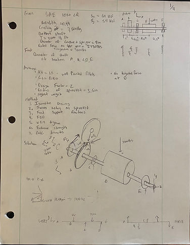
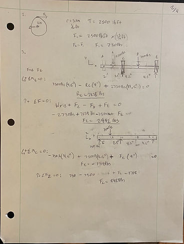
Analysis 5 was completed to determine the diameter of the shaft at the 5 different critical locations. This will allow for the shaft to not deflect more than the .05 inches while crushing the material. This required choosing a suitable material for the shaft (SAE 1020 CR), completing a statics analysis to find the support reactions, completing shear and moment diagrams, calculating the endurance limit, and then solving for the necessary diameters. Using a design factor of 2 the 5 minimum diameters that were found were: 1.69 inches, 2.08 inches, 2.94 inches, 2.91 inches, and 1.76 inches. These diameters will be increased to more suitable dimensions.
(Figure 5.1-5.4)
Analysis 6 was completed to determine if the shaft would fail due to the cyclic loading of crushing the carbon fiber. This ensures that the shaft diameter will not fail with the dimensions found in the previous analysis. This confirms the diameter that was chosen for the critical point of the shaft at where the crushing wheel is located. This was completed with the following steps: FBD, Shear and Moment diagrams, Calculating Stress, Endurance Strength, Goodman’s Criterion, and checking for Early cycle Yielding. It was confirmed that the 2.4 inch diameter at the critical point is ideal.
(Figure 6.1-6.2)
Analysis 8 was completed to determine if adding a center support to the housing frame would be sufficient versus thickening the housing plates to .35 inches. This was completed by finding the max deflection of the plate due to an experimental side load of 7500 lbs. for a 20X20 in plate and a side load of 3750 lbs. for a 20X10 in plate. The assumption was made that if a center support was added it would cause the housing to act as two separate plates. It was found that the addition of a center support with the .25 inch plate would minimize the deflection from .405 inches to .26 inches, an improvement of 35%. This improvement was determined to be sufficient and will keep cost down.
(Figure 8.1-8.2)
Analysis 7 was completed to determine the minimum required rotations per minute that will be needed to meet the feed rate requirement of 1 foot per minute. This was completed by determining the circumference of the smallest crushing wheel and then calculating the rpm. The needed RPM was found to be 0.47 RPM, this was compared to the new given RPM of 2.1 to determine it was sufficient.
(Figure 7.1)
Analysis 9 was completed to determine the correct key sizes for the sprocket, spur gear and the crushing wheel. This will ensure that the torque required to delaminate carbon fiber is transferred into the crushing wheel. It was completed by using Table 11-1 in Mott and then calculating the correct length needed. It was decided to use a key size of .875in X .875 in for all and the lengths came out to be 2.9 inches at the sprocket, 2.4 inches at the spur gear, and 1.7 inches as the crushing wheel.
(Figure 9.1)
Analysis 10 was completed to determine the specifications of bearings that will be needed for each side of the housing. This will ensure the system will not fail early and will help ensure the housing does not deflect the maximum of .1 in while crushing. This was done by calculating the design life of the bearings assuming it is a rotary crusher, calculating the basic dynamic load rating, and then finding a bearing number that surpasses the load rating. It was found at Location C a bearing number of 6310 will be needed and at Location E a bearing number of 6305.
(Figure 10.1)
Analysis 11 was completed to determine if 9/16 inch bolt is suitable to attach the bearings to the housing plates. This will ensure there is not more than the requirement of 15 ksi that is acting on the bolt. This was completed by finding the reaction forces in each bolt, the resultant force, and determining the max stress. It was found the max stress in a 9/16 inch bolt would be 12.6 ksi which is less than the 15 ksi, so that size of bolt will be sufficient.
(Figure 11.1)
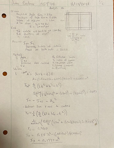
Analysis 12 was completed to find the needed thickness of the vertical angle iron supports. This will test the requirement of the vertical crossmembers being able to support a uniaxially load more than 3000 lbs. It was assumed that the angle iron behaved as a column that is fixed on both ends. This was done by calculating the moment of inertia of a 1.5 in X 1.5 in X 0.25 in piece of angle iron, determined the correct the column formula to use, it was determined to be a Long column so Euler’s formula was used. An angle iron support with the assumed dimensions would have a critical load of 3788 pounds, confirming that those dimensions are sufficient.
(Figure 12.1-12.2)
Analysis 13 was completed to find the tolerance values that were needed to complete the programming for the computer aided manufacturing of the crushing shaft. This was completed by designing to the industry standard of a basic hole and a RC8 loose running fit. The tolerance values were used from CHPT 13 of the Machine Elements in Mechanical Design textbook.
(Figure 13.1)
Description of Analyses
Figure 1
Crushing Force Required

Figure 2
Deflection of Crushing Shaft

Figure 3
Determining True Crushing Force

Figures 4.1-4.2
Determining Housing Thickness


Figures 5.1-5.4
Diameter of Shaft at Key Locations


Figures 6.1-6.2
Goodman's Yield Stress Check

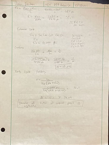
Figure 7.1
Needed RPM for Feed Rate

Figures 8.1-8.2
Determining Need for Center Frame Support
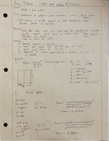

Figure 9.1
Determining Key Size

Figure 10.1
Determining Bearing Specifications

Figure 11.1
Determining Bearing Bolt Diameter
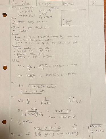
Figure 12.1-12.2
Determining Angle Iron Thickness